
By Dong Churl Lee – Senior HV Testing (Condition Monitoring) Engineer at Select Solutions
In late 2013, the failure of just one medium voltage (MV) transformer cable caused a major outage in a critical AusNet Services network, leading to the introduction of a more rigorous testing regime for all newly installed cables.
The regime requires all newly installed MV cables to be categorised by the asset owner considering their network contribution and also business impact in the event of service failure.
Cables determined to be “critical” to the business then need to be subjected to partial discharge (PD) testing as part of the commissioning program to ensure cables are correctly laid on site and installed according to the manufacturers’ instructions. This process gives cables the best chance of achieving their designed life expectancy.
PD is often referred to as a “cancer” in cables: once it is present, it tends to intensify and eventually lead to a failure.
Studies have found that the damage caused by PD depends on several factors and can range from negligible to causing failure within days to years.¹
As such, early detection is important. The philosophy behind the new test program is to control the risks of premature failure at the earliest stage possible.

Figure 1
Figure 1 shows a premature failure on a MV cable that has been in service for less than five years. The picture demonstrates a typical location of premature cable faults in a cable termination, which is at the end of the cable outer semi-conductive screen and the cable insulation.
PD can reside on or near the end of the cable screen if a smooth grading of electric field at the interface is interrupted by incorrect or careless assembly of the termination.
Some of the main factors causing the interruption are incorrect application of stress control materials, damage on the outer semiconductive screen and insulation, or introducing foreign objects such as voids, moisture or contamination during the assembly.
The premature cable fault shown in Figure 1 could have been prevented if PD testing had been performed in the commissioning stage.
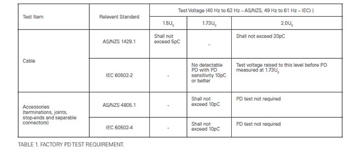
Factory PD testing on cables and accessories
In Australia, the common test standards for cables and accessories are Australian/New Zealand Standard (AS/NZS) and International Standard (IEC).
Each standard requires power frequency voltage of near 50Hz for PD measurement and specifies maximum allowable PD levels for Crosslinked polyethylene (XLPE) insulated MV cables and their accessories such as terminations and joints.2-5
XLPE cables have a number of advantages over paperinsulated leadcovered (PILC) cables and are now a mainstream of MV cables.
One disadvantage of XLPE cables, though, is that they are less tolerant to PD. The numbers, as outlined in Table 1, imply that even the smallest amount of PD could affect the life expectancy of the XLPE cable and the system – assembly of cables and accessories.
Cable manufacturers should ensure that all cables delivered to site are PD free by conducting PD testing on every single dispatch length in the factory.
Australian and international standards as well as most customers’ specifications require PD testing on every dispatch cable length as mandatory. Figure 2 demonstrates how the factory testing is performed on a dispatch cable length.
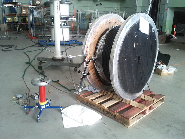
Figure 2. PD testing of cable on a reel.
Unlike cables, accessories can only be proven on site after installation because testing the accessories in the factory only certifies the assembling procedure.
It is not guaranteed that the same quality of workmanship will be reproduced on site during actual assembly of the accessories.
Hence, cable testing on site should be focused more on accessories, especially on the workmanship of the assembly.
However even with the small chance, PD in MV cables after installation is still a possibility and should not be ignored completely.
In 2014, Select Solutions – the business arm of AusNet Services – was engaged to implement AusNet Services’ test program to newly installed MV cables.
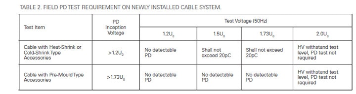
Based on the criteria in the standards, a field PD testing guideline was established as shown in Table 2. Considering that cables are assembled on site with less control of contaminations, the PD requirements were slightly eased. The aim is to have all post-installation cables categorised as “critical” meet these requirements.
Theoretically, if cables and accessories are correctly installed as per the design and the manufacturers’ instructions to the same quality performed in the factory, the cable system should satisfy the PD requirements in the table. However, field experiences have revealed that there are gaps.
Offline field PD testing using power frequency voltage
Cables are assessed using offline power frequency PD measurement technology. As the tests are performed at 50 Hz, PD activity in the cable system can be observed under the same conditions that exist in service. The tests are also carried out in the same way the cables and the accessories are tested in the factory. Hence, the field testing results on the cable systems should be comparable with their factory test results.
However, there are difficulties in performing power frequency voltage testing in the field. One of the main difficulties is that power frequency testing requires a large power supply due to the large capacitive current of the cable, and subsequently a large mobile test system is required. Select Solutions’ approach to tackle these problems is the use of a compactSF6 filled test transformer in conjunction with a tuneable reactor compensating the large capacitive current required by the cable (shown in Figure 3).

Figure 3a. 50hz cable test trailer (front).
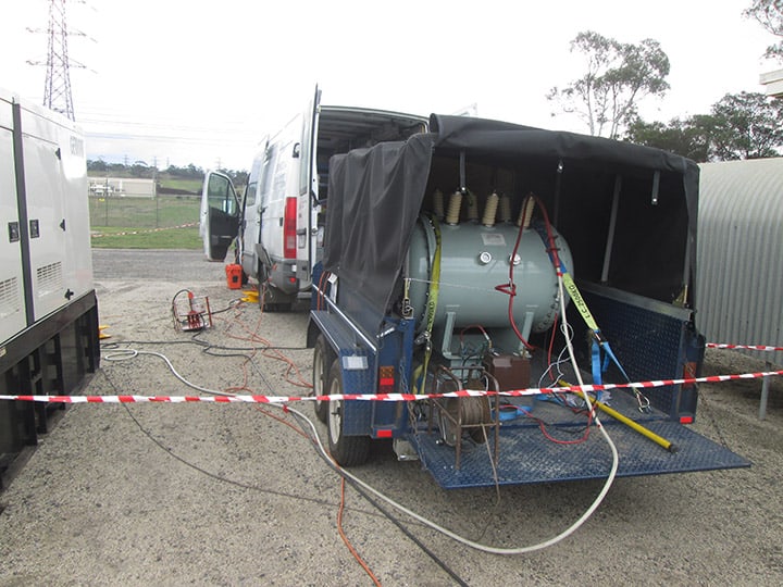
Figure 3b. 50hz cable test trailer (rear).
The test trailer is towed by a dedicated test van equipped with a controller for the test transformer and PD monitoring instruments. The test system is capable of energising up to 1km of 22kV rated cables at the high voltage withstand test voltage level of 25.4kV but with supply current of less than 20A at 415V. The required power was easily accessible from substation power points or a generator.
One challenge in field PD testing is mitigating electrical interferences. Especially in substations where PD measurement needs to be done near live apparatus, maintaining background noise to the desired levels of less than 20pC is often very difficult.
To tackle this problem, PD is measured at carefully chosen high-frequency ranges where signal to noise ratio is maximal. Often the measuring frequency has to be extended to more than 1MHz and sometimes even up to 3MHz to avoid strong interferences.
Even in that extended frequency range, it was found that the PD sensitivity was still very high with only 20 per cent to 30 per cent loss of sensitivity at the far end of the cable. With the aid of the advanced filtering technology, background noise levels of about 10pC to 20pC were achievable during field measurement.
It is important to locate the source of PD once it is detected in the cable system so that appropriate repairs can take place. Time Domain Reflectometry (TDR) is a primary method used for PD localisation. When cables are too short for this technology to work, acoustic PD detection method can be used.
Select Solutions found that PD quantities of as low as 100pC can be detected in cable terminations using ultrasound PD scanning.
However the sensitivity of the acoustic detection depends on the location and type of the defect in the cable terminations.
High voltage withstand testing is also conducted during the PD measurement.
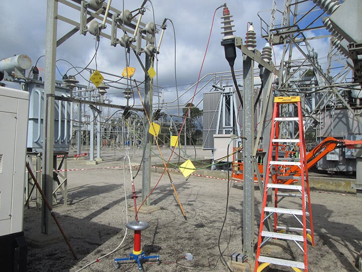
Figure 4a. Field PD testing on 22kv cables.

Figure 4b. Field PD testing on 22kv cables.
Prior to the high voltage withstand testing, PD measurement is conducted up to 1.73U0. Once a cable demonstrates acceptable levels of PD at 1.73U0, the test voltage is increased to 2U0 for the withstand testing.
After high voltage withstand testing, the test voltage is reduced to 1.73U0 and PD measurement is performed again, which is the most important part of the PD evaluation.
Once the cable passes this evaluation level with satisfactory PD performance, the cable is ready for service.
Test results and outcomes
This testing program has been in progress for the last three years and a total of 225 newly installed critical cables and individual cable cores have been tested during this period. 155 out of 225 cables, which is 69 per cent of all tested cables, have passed the PD requirements.
The other 70 cables (31 per cent) that did not pass the initial PD testing were repaired and subsequently retested before they were put in service.

Figure 5. Phase resolved PD pattern.
No cable has failed during high voltage withstand testing at 2U0. Most importantly, none of the 225 new tested cables have yet been reported for service failure.
One of the most critical components of cable terminations for PD performance is the stress control materials applied to the cable insulation and the semi-conductive screen. The majority of the terminations that were tested were heat shrink tube type and often reheating of the termination resolved the PD problem.
One of the reasons could be that heating of the termination helps the stress control materials to stick well to the cable.
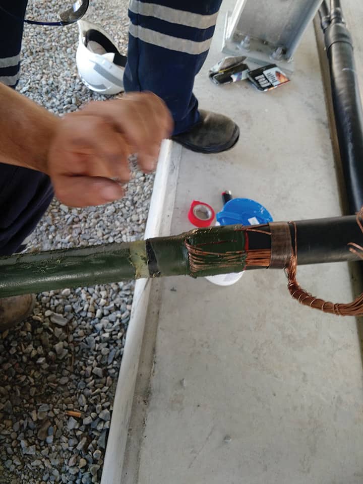
Figure 6. Retermination as a result of poor workmanship.
However, this does not work all the time. If PD does not improve after reheating of the termination, retermination of the cable should be seriously considered.
17 out of the total 450 tested terminations (3.8 per cent) had to be reterminated to pass the PD requirements. Only one cable (0.4 per cent) out of the total 225 tested cables had to be replaced due to PD presence.
Figure 6 shows PD in a 22kV cable due to damaged insulation as a result of poor workmanship during the assembly of the termination. It also demonstrates very low PD inception voltage. The cable had to be completely cut at the location of the damage and stripped again for retermination.
The PD testing program has also been educating cable jointers involved in installing the tested cables. The jointers are now more aware of the importance of their workmanship in cable assembly and their contribution to network reliability.
Select Solutions continues in 2016 to undertake AusNet Services’ test program for newly installed MV cables to help enhance the reliability of their power network.
References
1. IEEE Guide for Partial Discharge Testing of Shielded Power Cable Systems in a Field Environment, IEEE Power Engineering Society, IEEE Std 400.3 – 2006.
2. AS/NZS 1429.1:2006 Electric cables – Polymeric insulated Part 1: For working voltages 1.9/3.3(3.6)kV up to and including 19/33(36)kV, Australian/New Zealand Standard, 2006.
3. IEC 605022:201402 Edition 3.0 Power cables with extruded insulation and their accessories for rated voltages from 1kV (Um = 1.2kV) up to 30kV (Um = 36kV) – Part 2: Cables for rated voltages from 6kV (Um = 7.2kV) up to 30kV (Um = 36kV), International Standard, February 2014.
4. AS/NZS 4805.1:2007 Accessories for electric cables – Test requirements Part 1: Power cables with extruded insulation for rated voltages from 1.9/3.3(3.6)kV up to and including 19/33(36)kV, Australian/New Zealand Standard, 2007.
5. IEC 605024:201012 Edition 3.0 Power cables with extruded insulation and their accessories for rated voltages from 1kV (Um = 1.2kV) up to 30kV (Um = 36kV) – Part 4: Test requirements on accessories for cables with rated voltages from 6kV (Um = 7.2kV) up to 30kV (Um = 36kV), International Standard, December 2010.